Biomass Sensor
Background
Harbor Branch operates an Integrated Multi-Trophic Aquaculture (IMTA) system as part of its focus on Aquaculture research. Instead of just raising fish, the IMTA system also grows shrimp, clams, oysters, sea vegetables, and macro-algae. The additional species help digest nutrients from the fish waste and can be harvested as additional resources.
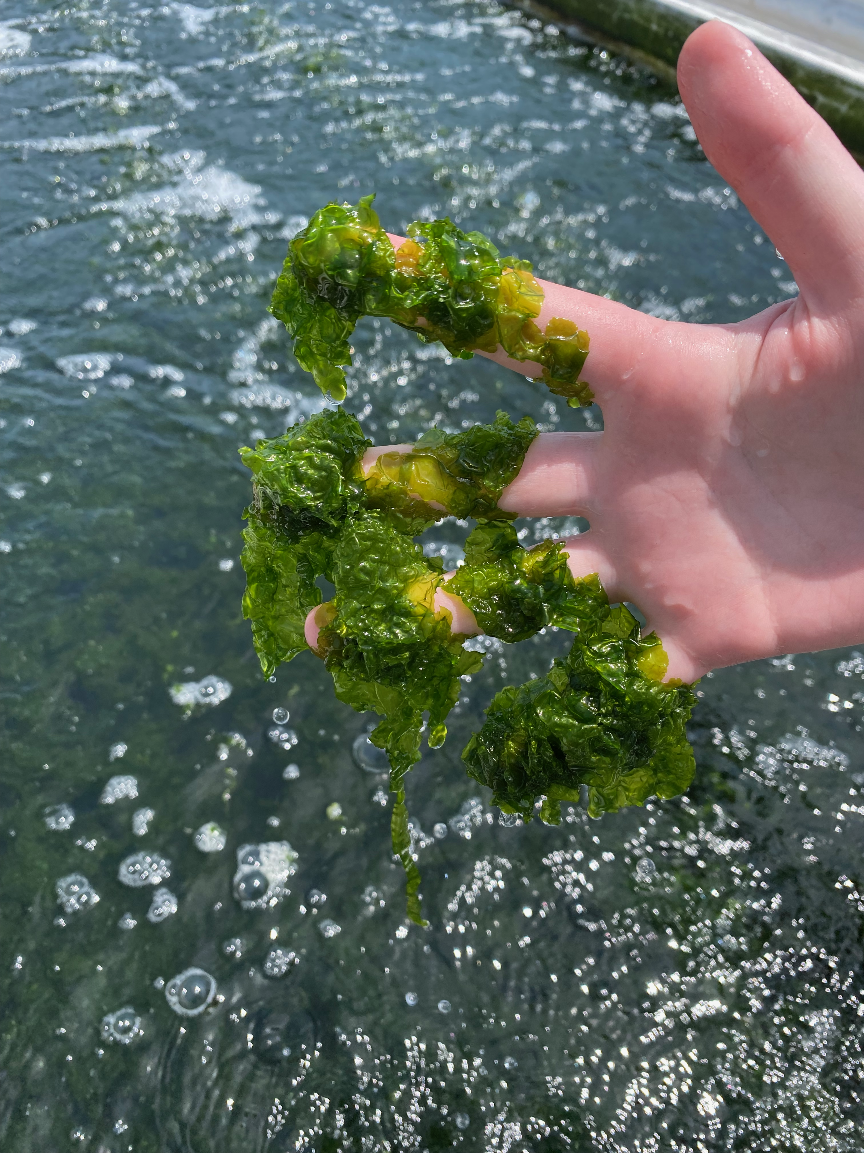
The macro-algae Ulva lactuca that is part of our IMTA system grows in outdoor tanks and helps process nitrates and ammonia from fish waste while also adding oxygen back to the system. The alga floats freely in pieces roughly an inch in diameter. Because the total amount of algae biomass in a tank can double in roughly a week, technicians have to harvest extra algae on a weekly basis to keep biomass levels optimal. Unfortunately, the only prior way to measure the total biomass of Ulva lactuca in a tank was by harvesting all of the algae, briefly drying it, and then weighing the algae by hand. This process is so time consuming, technicians have to resort to “eyeballing” biomass levels and making an educated guess as to how much algae should be removed to keep an optimal amount of biomass in the tanks.
Sensor Theory
Our lab set out to find a way to quantify the amount of Ulva lactuca in these outdoor tanks. We came up with a novel approach that uses an infrared (IR) light source and measures the amount of IR light reflected off of the algae. IR light cannot penetrate far through a body of water. With an empty tank and an IR light source located next to a receiver, the IR light would be fully absorbed by the water before it can bounce off an opposing tank wall and reflect back into the receiver. However, as the density of algae in the tank increases, the IR light is more likely to bounce off of a segment of algae and reflect back into the receiver before getting fully absorbed into the water.
Initial Prototype
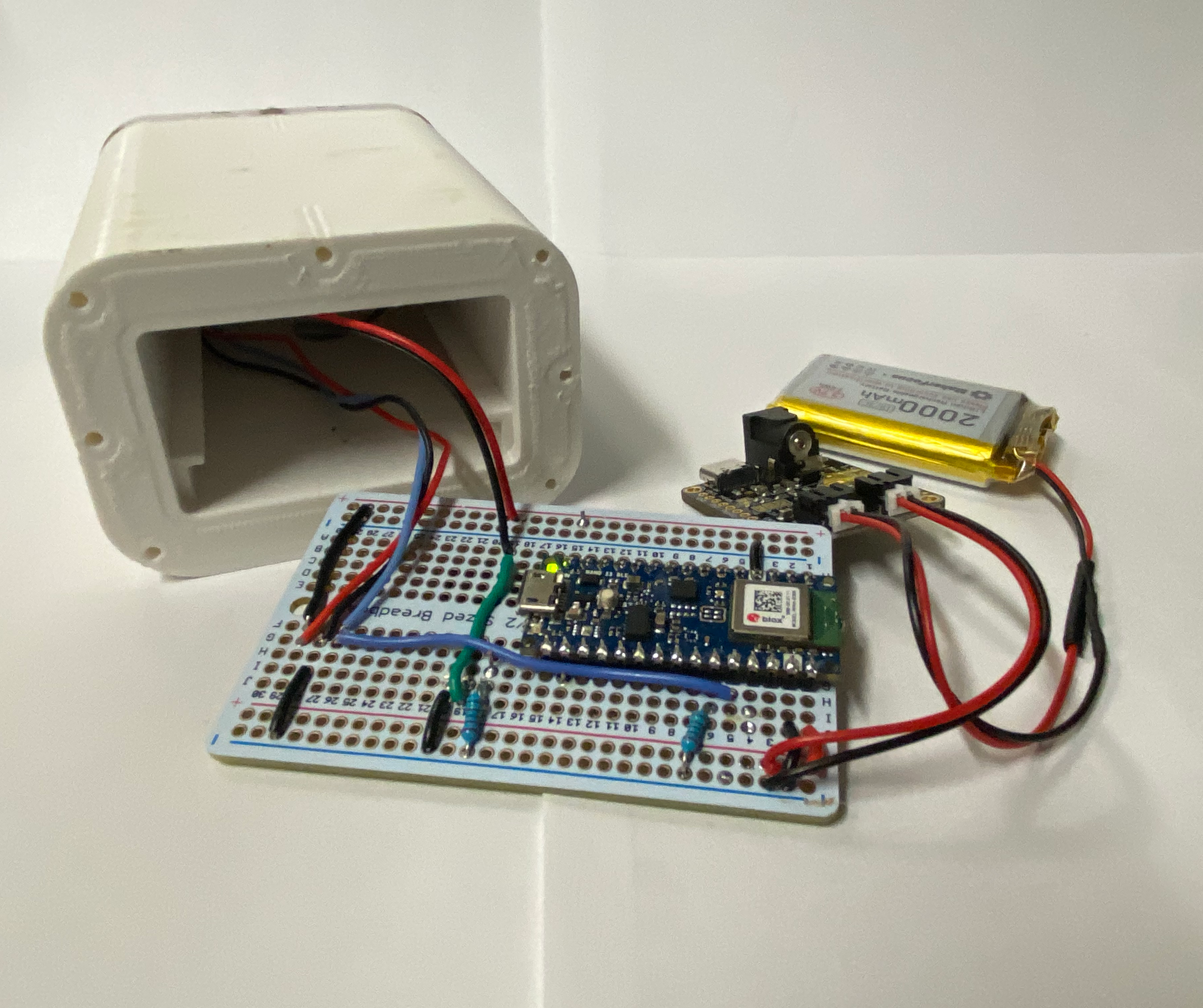
Because there were no previous sensors for this application I had to start with a clean slate when tasked with the design. All of the electronics for the initial prototype were assembled onto a proto-board. In an attempt to increase the battery life, a small solar panel and charging circuit were added to the sensor. The initial design worked well enough to suggest that our concept of measuring reflected light could correlate to biomass density. However, there were several issues with the design:
Issues (lots)
- Even with a small solar panel, the Arduino Nano 33 BLE board and IR laser could drain the battery in only a few days at a 20 minute sampling frequency. With dozens of sensors deployed, technicians would have to replace batteries constantly.
- If the battery had to be replaced, the entire waterproof housing would have to be disassembled and reassembled. This takes several minutes and, if done poorly, could cause a leak.
- The original idea of transmitting data over BLE to a nearby board was not feasible due to the drastically limited range when the majority of the sensor is submerged.
- The partially submerged sensor was a great trap for algae. Algae would clump around the sensor making the local measured density much larger than the actual tank density.
- The time required to manufacture the initial prototype was prohibitively high to make a sensor for every tank in our system.
Current Design
Being able to iterate on a design is critical to achieving a decent outcome. I was able to address most of the significant issues with the first prototype by taking a step back and re-thinking the system as a whole.
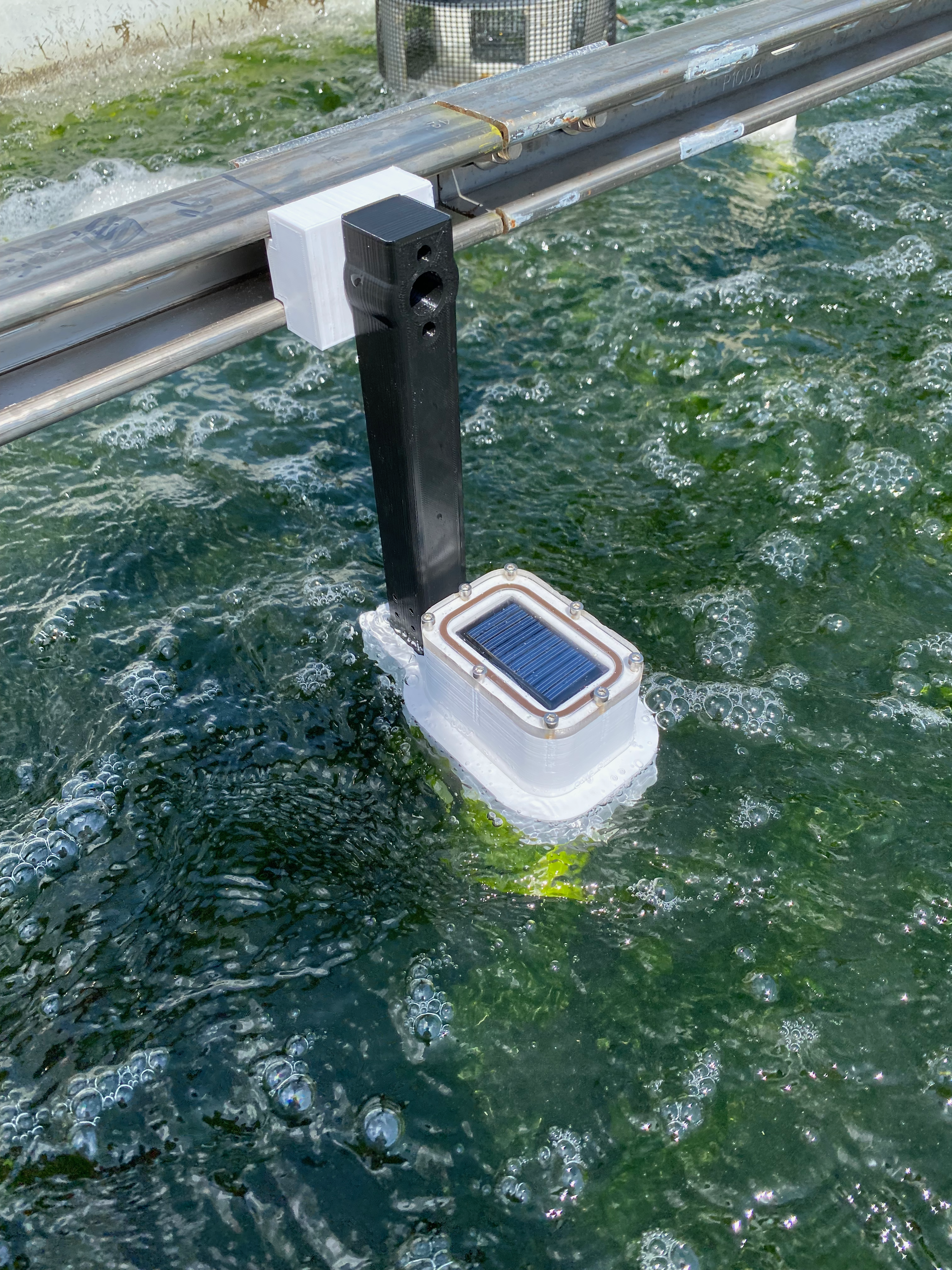
Two Housings, Not One
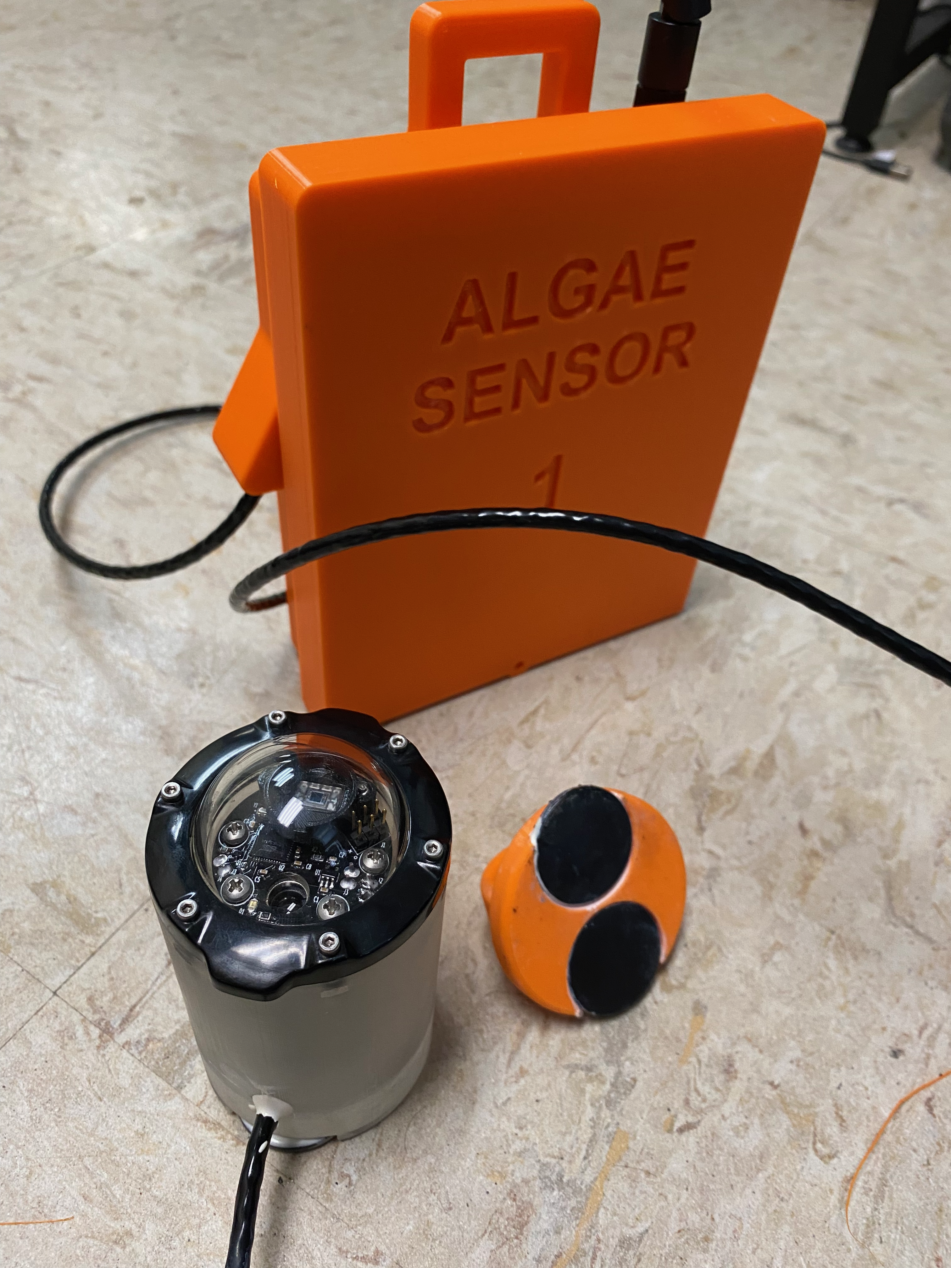
The largest mechanical change to make a functional biomass sensor was splitting the components into two different housings. The waterproof enclosure contained just the sensing electronics while the rain-proof enclosure houses the battery and radio transceiver. The rain-proof enclosure can be opened by sliding the lid off the enclosure: making battery swaps effortless. Because it is located fully out of the water, the radio can also achieve a better signal strength.
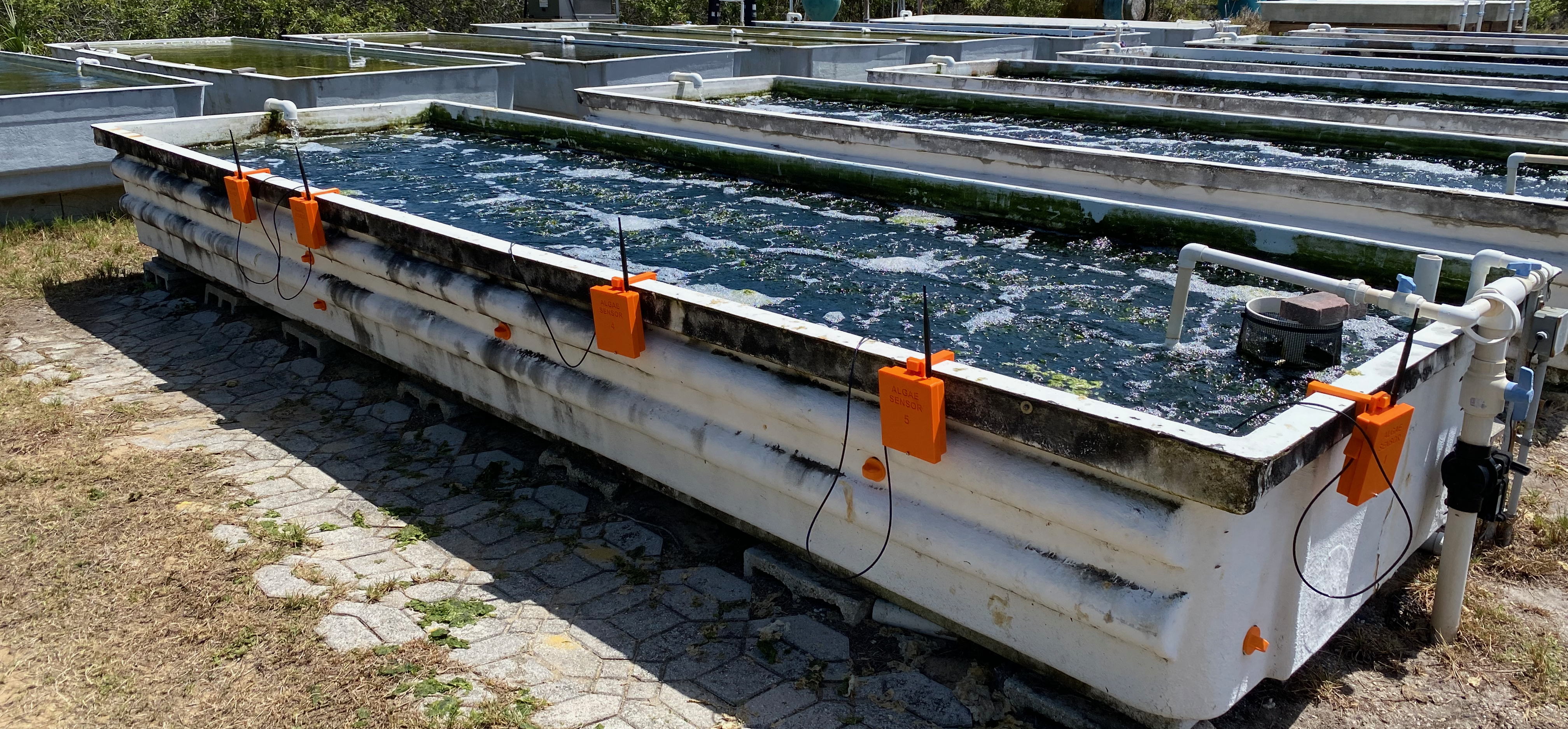
The sensor housing is considerably smaller thanks to a new PCB I designed to hold all of the electronics (more below). The housing has magnets embedded into the back of the enclosure that allow the sensor to stick to the side of the tank with the help of another pair of magnets on the outside of the tank (like an aquarium glass cleaner).
PCB
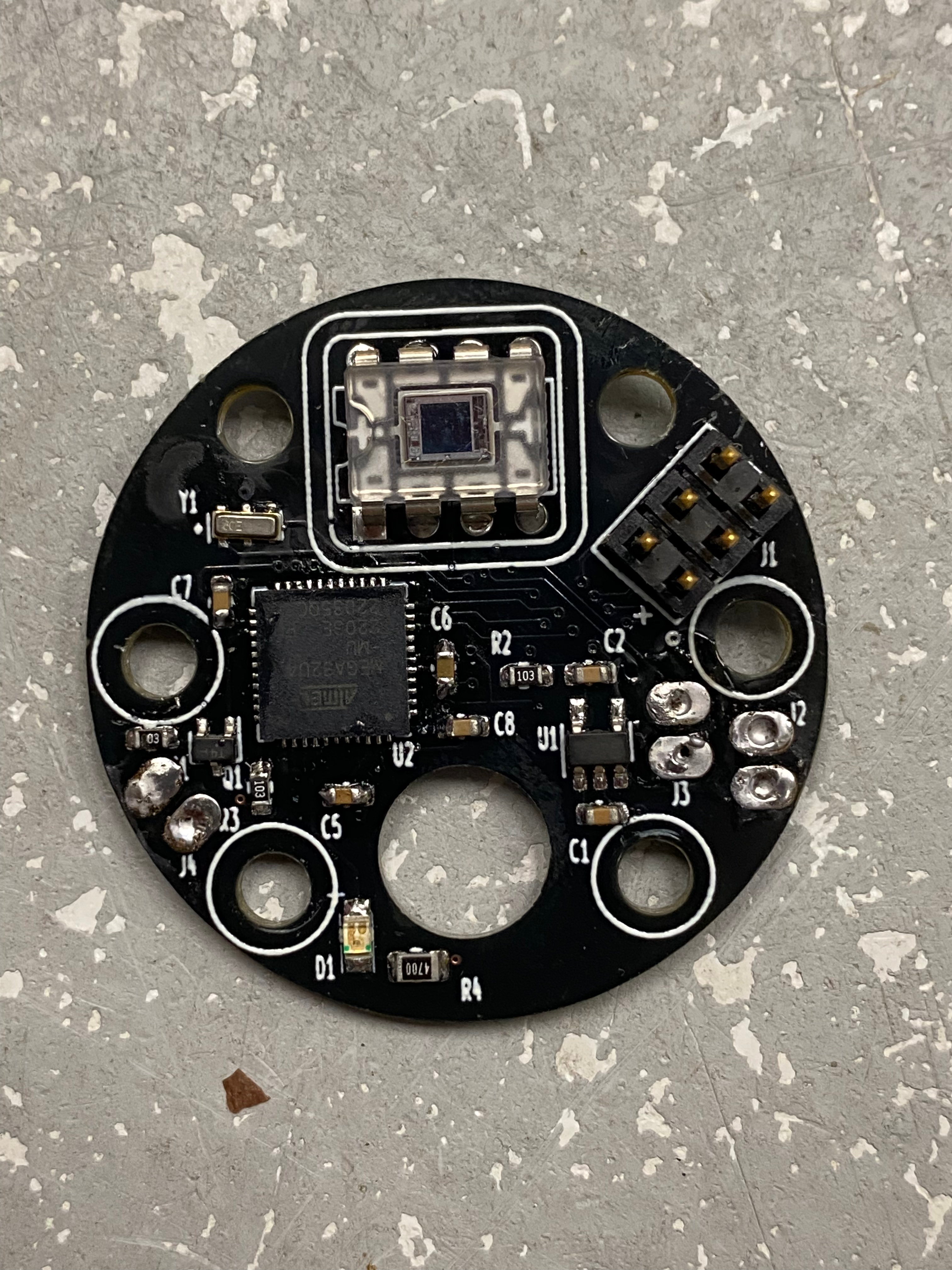
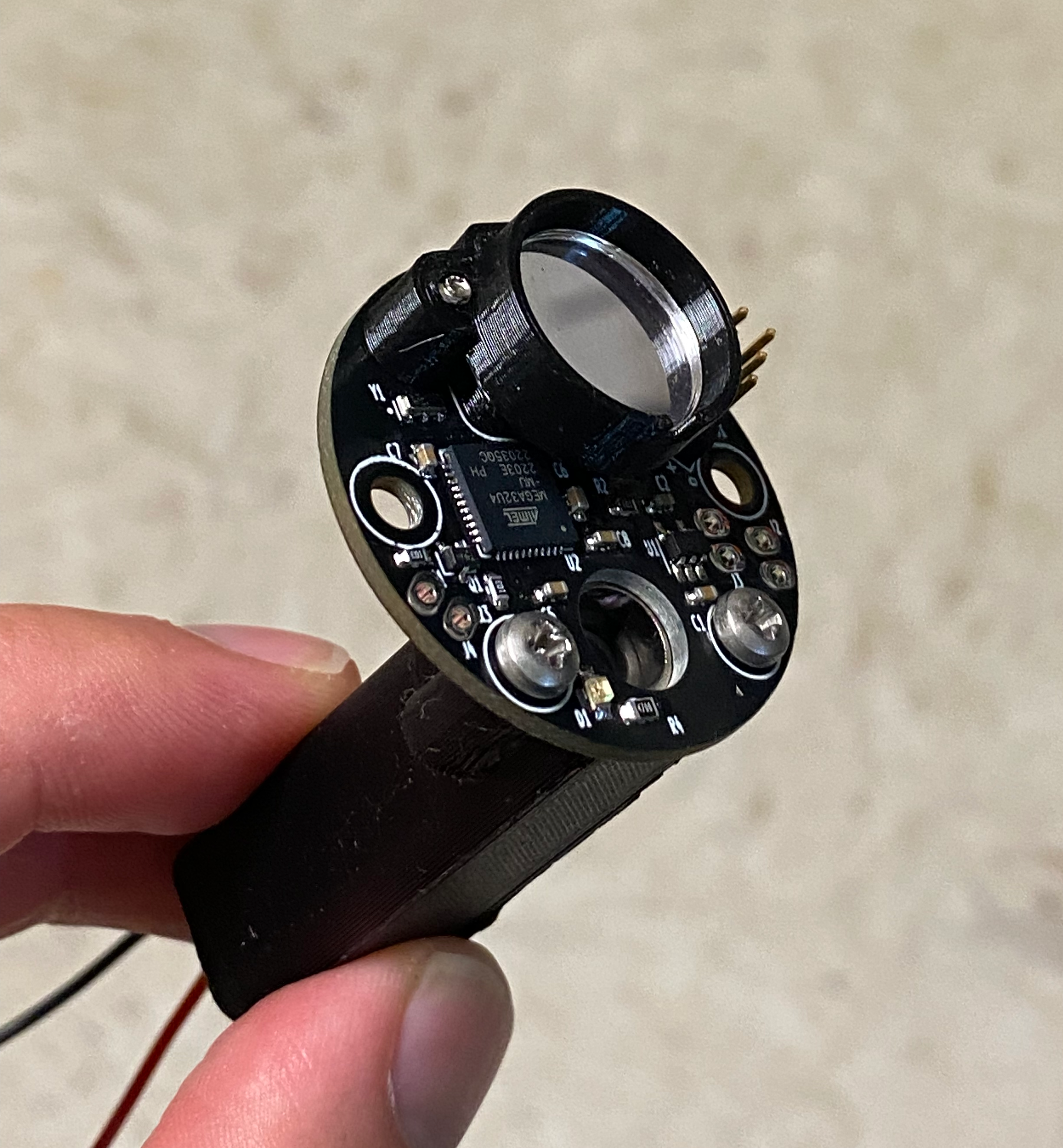
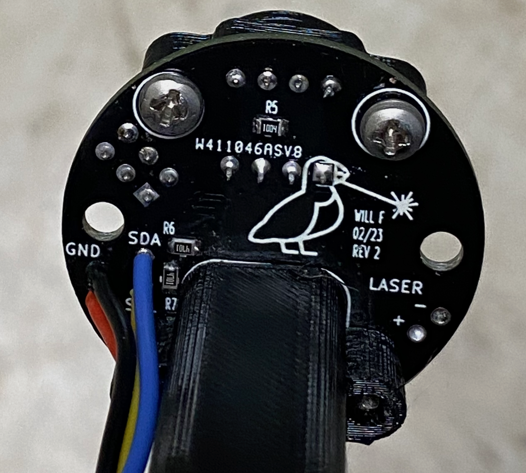
When trying to produce multiple units and miniaturizing a design, I usually make a PCB that contains all of my electronics. For the sensor, I was able to make a PCB that held all of the necessary electronics as well as act as a mount for the laser and bandpass filter that sits over the photoreceiver. This allowed me to shrink the internal diameter of the sensor to a little over 35mm. Moving away from the Arduino Nano 33 BLE board, I opted to use an ATMEGA32U4 microcontroller. While the ATMEGA32U4 may have fairly limited capabilities, the extensive use of the chip in popular circuit boards (Arduinos, Adafruit Feathers, etc) made it a suitable candidate for rapidly developing the PCB and implementing code to greatly reduce power consumption.
LoRa
The first prototype was unable to properly communicate in a sensor network. To be effective, the sensor has to transmit data through a pipeline that can eventually and easily be interpreted by technicians in the field. The primary challenges with the environment surrounding these tanks are:
- large distance between the tanks and surrounding buildings
- lack of nearby electricity or networking
This required a network that could send data over a fairly long range with limited power consumption. LoRa turned out to be an ideal candidate. We are able to transmit data 700 meters to an antenna mounted to the roof of our lab and the RFM95 module that we use in particular can be shutoff when not in use. The major downside to LoRa is a fairly limited bandwidth. However, this is not a bottleneck in our current system which at max would see a transmission every minute.
To make the LoRa network somewhat reliable, I utilized the RadioHead Packet Radio Library. This allowed me to implement the following features:
- Packet acknowledgements when data is successfully received by the basestation.
- Automatic retries spaced randomly apart when packets are not acknowledged.
Thoughts
The second sensor design proved to be robust enough to assemble and deploy 5 units. With code that puts all of the electronics to sleep between sampling periods, the battery life is solely correlated to the desired sampling frequency. At a sampling rate of 1 sample every 20 minutes, each sensor can last for 2 months before needing a recharge. As of the time of writing this post (Sept 2023) all 5 sensors have been in operation for 160 days without failure.
Now that data from these sensors is sent to a basestation that uploads the data to a Firebase Database, we can implement utilities that can make the data accessible and useful. This side of the project will probably make its way into another post soon.
Also, I like to put little birds on all my PCBs :)